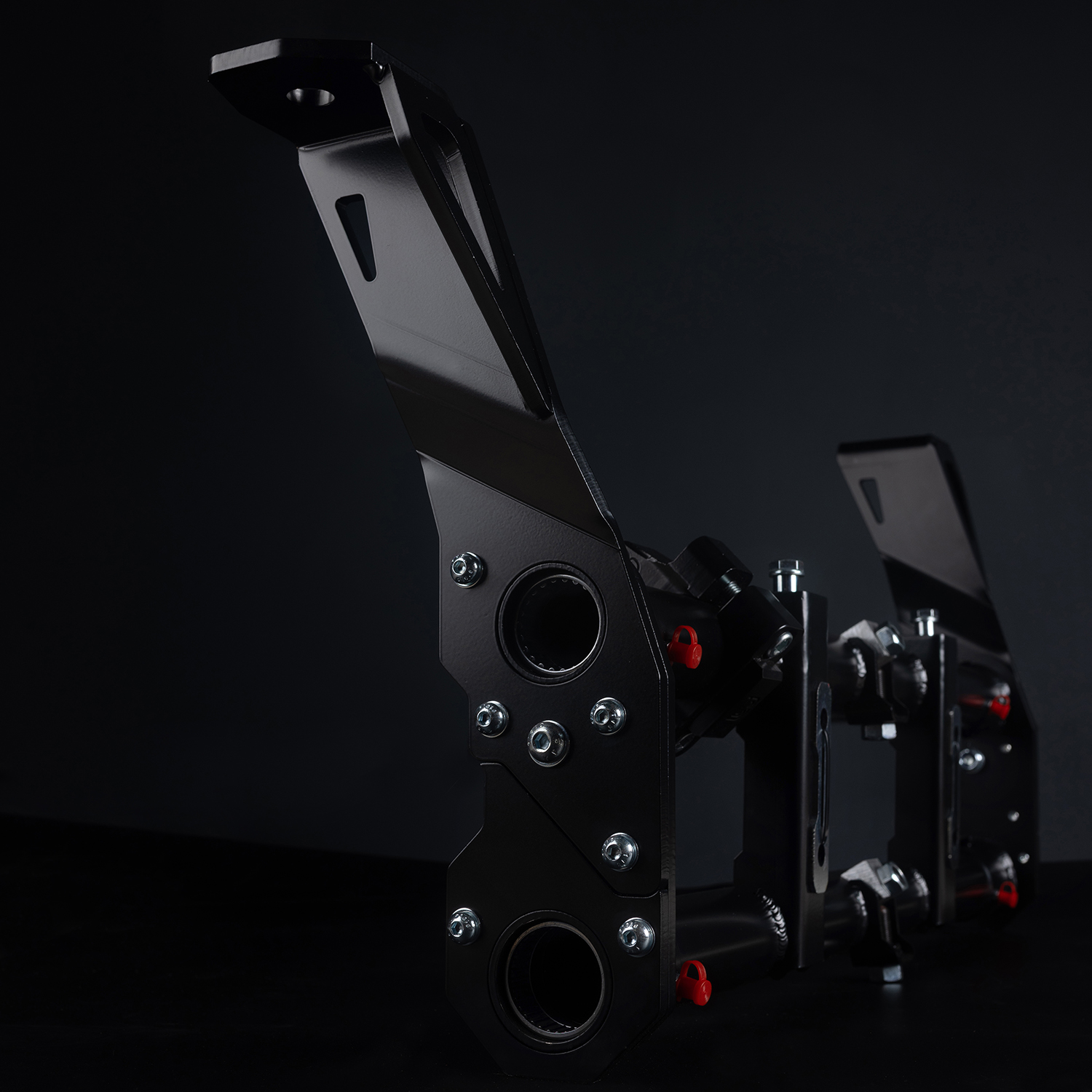
This guide applies to the following models:
– Type 1 (Beetle)
– Type 14 (Karmann Ghia),
– Type 181/ 182 (Trekker Thing)
Applicable to Standard Beetle torsion bar front suspension models (Link Pin and Ball Joint).
Note: Super Beetle (inc 1302/ 1303) models use MacPherson strut Front suspension setup and require a different procedure.
1. Identify Your Front Suspension Type
Link Pin Front End (typically up to 1965)
• Utilises king and link pins rather than ball joints.
• Spindles attach to trailing arms via link pins and shim packs.
• Correct shim arrangement is essential during assembly.
Ball Joint Front End (typically 1966–1979 Standard Beetle)
• Uses pressed-in upper and lower ball joints.
• Spindles connect to ball joints using tapered studs and self-locking nuts.
• Ball joints must be correctly oriented when pressed into trailing arms.
2. Tools and Equipment Required
• Trolley jack and axle stands
• Wheel chocks/wooden blocks
• Metric socket and spanner set
• Allen Key Set
• Breaker bar and torque wrench
• Ball joint separator (for ball joint models)
• Grease gun with suitable grease
• Replacement mounting hardware if required
• Rubber Mallet
• Grease (Red and Tacky “recommended”, Multipurpose is also suitable)
3. Beam Box Contents
| Hardware | Quantity |
|---|---|
| Beam | 1 |
| Shock Towers | 2 |
| Skid Ends | 2 |
| Beam Spreader Washers | 2 |
| M8 Dome Headed Bolt 20mm | 12 |
| M10 Dome Headed Bolt 30mm | 2 |
| M10 Nyloc Nut | 2 |
| M8 Spring Washer | 12 |
| M8 Washer | 12 |
| M10 Washer | 2 |
| M10 Cap Headed Bolt 30mm | 2 |
| Beam to Body Top Cap Fixings | 2 |
| M10 30mm Bolt (For Beam to Body Top Cap) | 2 |
| M10 Washers (For Beam to Body Top Cap) | 2 |
| Top Shock Fixing Bolts / Jam nuts OR washers (For Eyelet Towers Only) | 2 |
4. Front Beam Removal Procedure
1. Chock the rear wheels, loosen the front wheel nuts, raise the vehicle and support securely on axle stands.
2. Remove front wheels and brake assemblies. Support brake components to prevent strain on hoses.
3. Disconnect tie rod ends from spindles and pitman arm. Remove steering damper.
4. Remove front shock absorbers.
5. Disconnect sway bar clamps and brake line retainers attached to the beam.
6. Support the beam with a jack and remove the four main beam-to-frame head bolts.
7. Carefully lower and remove the beam assembly.
5. Front Beam Installation Procedure
Pre-Installation
Ensure all components covered in the beam box contents are present and position the main beam section face up on a workbench, we would recommend using a foam/ rubber worksurface to prevent scratches and damage to the beam as it is assembled. Remember as each component is installed the beam will become extremely heavy, we recommend assistance to move the beam once complete to install on the vehicle.
STEP 1 – Prepare the Adjusters
1. Remove the long bolts from the adjuster cores.
2. Back off the nut and bolt attached to the adjuster mounts.
3. Rotate the central core to access the second pinch bolt.
4. Back off this bolt to create a clear path for the torsion leaves / through rods.
⚠ Do NOT fully remove this pin yet — it holds the core in place during installation.
STEP 2A – Torsion Leaves
1. Split each torsion leaf stack into individual leaves.
o Important: Maintain original order and orientation.
2. Grease each leaf individually.
3. Reassemble the leaf stacks.
4. Secure both ends of each stack using cable ties.
STEP 2B – Through Rods
1. Install the through rod as you would a set of leaves, however ensure the rod is rotated so that the dimple is central.
STEP 3 – Align & Install Torsion Leaves
Orientation Note (1966–79 Ball Joint Arms):
• Left side arms: Pinch bolts face upward
• Right side arms: Pinch bolts face downward
1. Ensure the central dimple faces upward.
2. Confirm both leaf stacks are installed in identical orientation.
3. Slide the leaves through the beam core.
4. Remove the short central pin fully.
5. Align the leaf dimple with the hole.
6. Secure the pinch bolt.
7. Lightly grease and reinstall the central pinch bolt.
8. Leave pinch nut loose for now.
9. Repeat for both top and bottom tubes.
STEP 4 – Assemble Shock Towers
1. Use supplied M8 Allen bolts with spring and flat washers.
2. Install removable shock towers.
3. Tighten all bolts securely. (28 Nm equal to 20.65 ft-lbs)
4. Fit the M10 Tower Securing Bolt through the central hole in the tower and secure (28Nm equal to 20.65 ft-lbs )
STEP 5 – Install Skid Ends
1. Fit skid ends to both sides.
2. Tighten and secure. (28 Nm equal to 20.65 ft-lbs)
(Note: Skid ends are replaceable wear components.)
STEP 6 – Install Grease Seals
1. Push grease seals fully into place.
2. Ensure seal sits flush, remember the steel / solid side goes into the beam, and the soft tapered edge goes up against the trailing arm.
Note: On Link Pin Model Limebug Beams, you will require 4x Ball Joint (66-) Upper Grease Seals, these are used as they are significantly better design than the earlier seal and locate fully into the beam tube.
3. Optional: Apply PU sealer to beam face to prevent internal grease escape.
Beam is now complete up to torsion leaves / through rods.
STEP 7 – Install Trailing Arms
1. Pre-grease race surfaces.
2. Slide trailing arms into position.
3. Rock slightly to engage leaf stack.
4. Check alignment:
o Central pinch bolt should sit at 90° to trailing arm pinch bolt on ball joint models and 180° on Link pin models.
5. Look through threaded hole to confirm dimple alignment.
6. If installing through rods, ensure to Remove the Trailing arm end caps for Ball Joint models prior to fitting the trailing arms, this can be done by using a piece of bar or long screwdriver and a hammer to tap the cap off, this will ensure the correct location of the pinch bolts at the next step.
Note: Limebug offers a bolt on trailing arm end cap option to prevent dirt ingress, we offer this for all makes/ models of
aircooled VW including ones which would never have originally been fitted with a cap.
Note: Link Pin Trailing arms are often damaged on the end where the through rods will stick through, ensure the bolt securing the roller end is not “tight” in this aperture before completing the trailing arm install. If it is tight be sure to sand this out slightly, this is only an issue where the arms have had excessive impacts with a
hammer typically.
Ensure grease seal compresses evenly as the trailing arm is fitted.
STEP 8 – Install Pinch Bolts & Nuts
1. Pre-grease threads.
2. Install pinch nuts in fully backed-off position.
3. Tighten pinch bolt.
4. Tap trailing arm lightly.
5. Retighten bolt, note this bolt must NOT be overtightened, as a general guide the torque should be 32 Nm equal to 23.65 ft-lbs.
6. Lock pinch nut.
7. Repeat for opposite side.
STEP 9 – Camber / Castor Nut Installation
1. Pre-grease camber nut.
2. Mount spindle to lower ball joint (Secure using M12 Nut)
3. Install camber nut on the upper ball joint with large retaining washer, do NOT use an off the shelf washer or the trailing arm may work free, leave the Nut Loose for now to allow Camber/ Castor to be set.
Base Setting (Recommended Start Point):
• Set to maximum castor.
• Rotate camber nut so maximum material faces rear of vehicle.
• Align flat edge perpendicular to rear of spindle.
• Tighten with 19mm nuts.
Repeat opposite side
STEP 10 – Install Gas / Oil Dampers
1. For Ball Joint Static models, Remove top nut, washer and one urethane mount.
2. For Link pin models and Ball Joint Lowers, Press lower steel tube into shock.
3. Seat flush side toward trailing arm.
4. Install 10mm nut & washer.
o Tip: Use low profile M10 nut for full nylock engagement.
5. Tighten all nuts.
Note: For air ride setups, ensure the top mount is installed using the double nut method. This is achieve by inserting the bolt onto the shock top mount, then winding the jam nut onto the bolt but leave a tiny gap (approx. 0.2mm) so the shock can rotate freely about the bolt. Next wind the bolt into the shock tower and
once the jam nut hits the tower tighten it against the tower.
Repeat both sides.
STEP 11 – Secure Adjusters
1. Set adjuster approximate height by raising/ lowering the adjuster foot mount in the centre of the beam. As a general rule, we recommend setting this to maximum height initially and then once on the vehicle turning anticlockwise to lower the vehicle to reach the desired ride height. Remember once an occupant enters the
vehicle the ride height will most likely change also.
2. Tighten adjuster bolt, Lock pinch nut.
3. Confirm all 19mm nuts are tight.
STEP 12 – Track / Tie Rod Assembly
1. Identify:
o 2x Left-hand thread nuts
o 2x Right-hand thread nuts
o 4x jam washers
2. Pre-grease threads.
3. Fully seat nuts and washers.
4. Wind tie rods fully home (ensures even adjustment later).
5. Grease taper heads lightly.
Rod Orientation:
• Long rod Inner (Connects to Pitman Arm) = Tie Rod End has damper eye mount
• Short rod Inner (Connects to Pitman Arm) = Cranked (Angled Head)
6. Secure using Allen locker while holding with 19mm spanner for late models and 17mm for early models. Adjust rod length to a position where the wheels look straight. Revisit this once assembly is completed to ensure alignment is correct.
STEP 13 – Install Damper Mount
1. Split mount.
2. Mark position from outer edge of beam upright:
• 55mm – LHD models (Measurement From Right Side of Right Beam Upright)
• 15mm – RHD models (Measurement From Left Side of Left Beam Upright
3. Reattach rear mount.
4. Mount may be rotated to suit the setup (typically when using Ultrarm or running air, tie rod angle will be higher than original, hence rotate the steering damper mount to sit more horizontal (lower). If running stock height steering damper mount can sit closer to the stock 35 degree angle upwards as fuel tank clearance
will be less critical.
STEP 14 – Fit Steering Damper
1. Attach to tie rod first.
2. Then attach to damper mount.
3. Use:
o Lock washer (tie rod side)
o Spring washer (mount side)
Beam assembly is now complete up to spindles.
Note: To complete procedure fully grease all components via the grease nipples/ zerks installed on the beam and spindles (Link Pin Models).
Complete initial test drive and recheck/ torque all bolts and fixings.
6. Torque Specifications
| Component | Torque (ft-lb) | Torque (Nm) | Notes |
|---|---|---|---|
| Front beam to frame head bolts | 36 | 49 | Main mounting bolts |
| Steering damper to beam bolt | 29–32 | 39–43 | Damper bracket fixing |
| Steering damper to tie rod nut | 18 | 24 | Damper to tie rod |
| Tie rod end nut (M10) | 18 | 24 | Where M10 stud fitted |
| Tie rod end nut (M12) | 22 | 30 | Where M12 stud fitted |
| Tie rod clamp bolt | 11 | 15 | Clamp type tie rod adjuster |
| Torsion arm grub screw and locknut | 29–36 | 39–49 | Secures torsion leaves |
| Shock absorber upper mounting (M10) | 14 | 19 | Where M10 bolt fitted |
| Shock absorber upper mounting (M12) | 22–25 | 30–34 | Where M12 bolt fitted |
| Shock absorber lower mounting | 22–25 | 30–34 | Lower torsion arm fixing |
| Ball joint to spindle nut (M10) | 29–36 | 39–49 | Ball joint models |
| Ball joint to spindle nut (M12) | 36–51 | 49–69 | Ball joint models |